
Featured snippet: A deep, narrow milled slot costs more when its width forces a small cutter to reach far below the top surface. Tool deflection, chip evacuation, step-down passes, wall finish, and inspection can then dominate the quote; widening the slot, reducing its depth, or opening one end often lowers cost without changing the required function.
Introduction
Two aluminum brackets can have the same mass and nearly identical outside dimensions, yet receive very different CNC quotes. The expensive one may contain a single narrow channel extending deep into the block. The engineer sees a simple rectangular subtraction in CAD. The machinist sees a small end mill on a long reach, limited chip clearance, multiple passes, and a feature that may be difficult to measure at its floor.
For a buyer close to issuing an RFQ, deep narrow slot CNC milling cost is therefore a design question, not just a machine-hour question. The slot’s width, depth, length, end condition, material, and functional tolerances determine which tool can reach it and how slowly that tool may have to cut. This guide explains the practical trade-offs and the drawing information a supplier needs to quote with confidence.
Lauens CNC lists custom CNC milling for parts with pockets and slots, with routing reviewed against tool access, workholding, and finish needs. The appropriate process and price for any specific slot must be confirmed from its CAD model, drawing, material, and quantity. No universal depth-to-width ratio guarantees a quoted result.
Technical Deep-Dive
Slot width controls the cutter; depth controls its reach
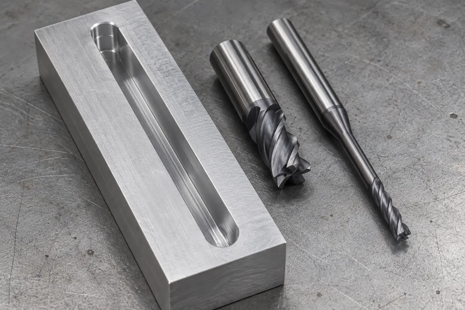
In a conventional open-top slot, the cutter must fit between the walls. A narrower slot limits tool diameter, while a deeper slot demands enough flute length and neck clearance to reach the floor without the shank or holder striking the part. The combination is what makes the feature difficult. A wide shallow pocket can often be roughed aggressively with a stiff tool. A narrow deep slot may require a slender end mill, reduced engagement, staged depth cuts, and a separate finishing pass.
Longer tool projection increases susceptibility to bending and vibration. At full-slot engagement the cutter sees material on both sides, so the cutting load and chip flow differ from light side milling. The actual stable cutting parameters depend on tool geometry, holder, machine, alloy, coolant or air strategy, and the slot’s geometry. A responsible quote should not promise a fixed feed-rate multiplier from a rule of thumb. The supplier must choose a route and, for demanding features, validate it on the real part or a representative setup.
The end condition matters too. An open-ended channel lets the cutter enter or leave the material along its length and can make chip removal easier. A blind-ended slot requires entry within the feature and leaves a radius at the end equal to the cutting tool’s path and shape. If the drawing requires a perfectly square inside end, ordinary end milling cannot produce it directly. A design change, mating-part relief, or a separate process may be necessary. Do not ask the supplier to infer whether the visible square corner in a CAD model is functional.
Chip evacuation and floor finish
Chips trapped in a deep channel can be cut again, damaging the floor, marking the walls, or breaking a small cutter. The process may need frequent retracts, a suitable air or coolant delivery method, and staged roughing that preserves space for chip flow. In aluminum, a built-up edge or smeared material may spoil a cosmetic or sealing floor. In stainless steel, heat and tool wear can narrow the safe cutting window. The tool path, not just the nominal feature volume, drives cycle time.
Finish requirements should identify the surfaces that actually matter. If the channel is a cable passage, a burr-free entry and clearance width may be critical while floor texture is not. If it is a precision guide or bonding land, wall straightness, floor roughness, and positional relationship to a datum may matter. Calling out a fine finish everywhere can add a slow final pass and difficult inspection without improving the assembly. Define the functional faces and allow ordinary milled finish elsewhere.
| Slot design choice | Likely process effect | RFQ information needed |
|---|---|---|
| Wider, shallower open-top slot | Allows a stiffer cutter and easier chip removal | Minimum functional width and depth, not only nominal CAD geometry |
| Deep slot with narrow width | Requires long-reach tooling, multiple depth passes, and careful vibration control | Width, depth, length, floor condition, and material grade |
| Blind-ended slot | Entry and end-radius constraints may slow cutting | Whether the end radius is permitted or an alternative end geometry is acceptable |
| Open-ended channel | Can improve access and chip exit, depending on the part | Whether an end may break through without affecting assembly |
| Critical wall and floor finish | May add finish passes and dedicated measurement | Specific functional faces, roughness, datum, and acceptance method |
The table is qualitative. A wider slot may still be costly if it sits behind a tall wall or requires a complex fixture, and a narrow slot may be routine if it is shallow and short. The point is to make the constraint visible before the supplier chooses tools.
Measurement can be as difficult as cutting
A caliper placed across the top opening may not prove that the slot is the correct width at the bottom. A long slender probe can be needed to inspect the lower walls; a floor depth measurement may require a suitable datum and accessible probe path. If the slot is part of a mating assembly, a functional gauge or sample mating part may give better information than a blanket tight width tolerance. The drawing should distinguish the entrance width, minimum clear width through the working depth, floor depth, and any critical straightness or parallelism.
Inspection scope also changes with batch size. For prototypes, the buyer may want a full dimensional report to validate the design. In production, selected critical dimensions and a documented sampling plan may be more appropriate. The supplier should quote the specified level of inspection, not guess whether the buyer expects every wall and floor to be recorded on every part.
Design for Manufacturability (DFM) Guidelines
1. Dimension the function, then relax the unused volume
Ask what actually occupies the slot. A cable, key, guide pin, adhesive, fluid channel, or clip each imposes different needs. If only the upper portion engages a mating feature, the lower portion may not need the same precision width. If the channel is only a clearance feature, an extra fraction of width could allow a much stiffer tool. These changes should be evaluated against the assembly, not adopted blindly for machining convenience.
2. Shorten the required depth where possible
Deepen only the region that performs the function. A long full-depth groove may be replaced by a shallower general channel and a short deep pocket where a component seats. Reducing the depth can permit a shorter tool stick-out and fewer step-down passes. If the part needs a constant-depth floor for flow or guidance, specify that requirement; if it does not, avoid making the entire channel critical because one local feature is critical.
3. Permit a realistic end radius and entry
An end mill leaves radiused internal ends. If a square-ended mating tongue must slide fully into the slot, relief can often be placed on the tongue or at the slot end, subject to the functional design. A small lead-in chamfer may protect the mating component and ease deburring. Conversely, a vague “sharp corners” note can force an unnecessary secondary operation. Mark the exact corner that needs special treatment and explain the assembly reason.
4. Consider an open-end or split-part redesign
If the slot is open at one end, a tool may have a cleaner approach and chip exit. If a deep internal channel is inaccessible or difficult to inspect, a two-piece assembly with a milled shallow channel in one half may be worth comparing. That introduces fasteners, a joint, and assembly labor, so it is not automatically cheaper. Request both routes when the production quantity and functional requirements justify a design study.
5. Protect the remaining wall and the clamping datums
A deep channel leaves slender adjacent walls. These can move under cutting force or clamp pressure, changing width after release. Provide a sensible holding surface on the outside of the part and avoid placing the slot immediately beside a thin outer edge unless necessary. When flatness or position relative to mounting holes matters, define those datums explicitly. A shop can then plan the roughing, stress relief if needed, finish pass, and inspection sequence around the real interface.
6. Separate burr control from a cosmetic finish demand
Deep slots deserve careful edge control because loose burrs can interfere with mating parts or break free in service. Specify a clean entrance, safe edge break, and any no-loose-chips requirement. That does not mean every interior wall needs a polished surface. If an anodized part will be assembled into a tight clearance, include the finishing allowance in the drawing and identify whether the finished or pre-finish width is controlled. Anodizing tolerance issues should be reviewed separately from the slot’s machining tolerance.
A useful RFQ package includes a STEP model, a controlled 2D drawing, alloy and temper, quantity tiers, finishing requirements, and an explanation of the slot’s purpose. Show the mating component or a simplified interface if possible. For deep narrow slot CNC milling cost, this context helps the estimator tell a truly necessary tight feature from a CAD default that can be changed at low risk.
Cost Breakdown & Economics
Why material removal volume is a poor predictor
A narrow slot removes little metal, but low material volume does not imply low cost. A small cutter may need many axial steps and slower feeds; chip clearing and cautious finish passes consume time. The quote can include a long-reach tool, tool wear allowance, and inspection method. If a tool breaks deep in the slot, recovery or scrapping can be expensive. The supplier prices this process risk as well as nominal cycle time.
At prototype quantity, programming, fixture setup, selecting a stable tool, and first-piece verification can dominate the unit price. At production quantity, the repeated cutting cycle, tool life, chip management, loading, and measurement become more important. Ask for realistic prototype and repeat-order quantity breaks. A design that is affordable for five validation parts may have a poor long-run unit cost if every production part needs a slow deep finishing pass.
Material, geometry, and tolerance interact
Aluminum, stainless steel, and engineering plastics require different cutters and cutting strategies. Some plastics can deflect or burr; stainless steels may increase heat and wear. The exact alloy and condition matter. Slot width alone does not determine price; length, depth, access from the top, nearby ribs, remaining wall thickness, and blind-end geometry all interact with it. A narrow slot next to an open edge may be easier to cut than a nominally wider slot buried behind a tall pocket wall.
Tolerance should be applied only where the mating part requires it. A minimum clear width along the full working depth might be essential for a sliding key. Tight parallelism of both walls could be unnecessary for a wire passage. The first requirement may demand a suitable probing or gauge approach; the second can add machining and inspection cost for no gain. If the fit is critical, send the mating-part tolerance stack so the supplier can review a workable target rather than merely quoting the tightest number in isolation.
| Cost factor | What it adds to the route | Buyer action |
|---|---|---|
| Small width combined with large depth | Long-reach cutter, reduced stiffness, staged cuts | Confirm the minimum usable width and whether any section can be widened |
| Long full-depth channel | More cutting time and repeated chip evacuation | Deepen only the functionally required region if the design permits |
| Blind end or square-corner demand | Constrained entry and potentially a secondary process | Approve a realistic end radius or provide a mating-part relief |
| Fine wall or floor finish | Additional finish passes and possible hand work | Mark only the functional surfaces and required roughness |
| Tight deep-width tolerance | Slower finishing and harder bottom-of-slot measurement | Define the working depth and acceptance method |
| Thin remaining walls | Clamping and cutting distortion risk | Provide adequate holding lands and functional datums |
| Low quantity | Setup and first-piece effort spread over few units | Request prototype and production quantity tiers |
When comparing two supplier quotes, confirm they include the same material, finishing condition, slot acceptance criteria, deburring, and inspection scope. A lower price may reflect a broader slot tolerance or a different interpretation of the blind end. Ask the supplier to flag any assumptions and to identify the largest cost driver. That conversation often yields a design change more valuable than negotiating a small discount on an unchanged process.
Alternatives such as wire EDM, saw cutting, or a split assembly can be considered when the required geometry cannot be milled efficiently. Whether they are economical depends on material, slot shape, surface requirements, quantity, and the supplier’s actual capabilities. Do not place an alternative process on the drawing without engineering review; provide the functional constraint and ask for a manufacturable option.
Conclusion & Call to Action
The fastest way to improve a deep-slot RFQ is to clarify which dimensions and surfaces make the feature work. In practice, deep narrow slot CNC milling cost rises when a small tool needs long reach, chip flow is restricted, walls move, or inspection cannot access the lower feature. A little more width, less depth, an open end, or a permitted end radius may change the route substantially while preserving the assembly’s purpose.
Upload your 3D CAD file and drawing to Lauens CNC for a free DFM review and prompt quote. Include the material, quantity tiers, finish, mating-part clearance, critical slot dimensions, and acceptance method. Those details allow the team to review your actual geometry and identify the tooling, tolerance, and cost decisions before you commit to production.


