
Ausgewählte Antwort: CNC machined impeller cost is driven mainly by blade accessibility, starting stock, material, roughing volume, finish tool reach, balance requirements, bore-to-blade relationships, inspection scope, and quantity. The most useful RFQ combines a revision-controlled 3D model with a drawing that identifies the functional datums, controlled blade surfaces, bore fit, runout, finish zones, and any balancing requirement.
An impeller is not expensive merely because it looks complex. It becomes expensive when the geometry forces long, delicate tools; when a closed or deeply overlapped passage blocks access; when every blade needs a fine finishing toolpath; or when the buyer asks the supplier to prove profile, runout, surface condition, and balance without defining how those items will be accepted. For a purchasing team, the fastest path to a comparable quote is to separate the part into functional zones and state which zones truly control performance.
This guide explains how a machining supplier evaluates an open impeller, where 3-axis, indexed 3+2, simultaneous 5-axis, turning, and secondary operations may fit, and how design and drawing decisions change the economics. It is written for engineers and buyers who already have a pump, compressor, blower, or fluid-handling component to source and want fewer assumptions in the quotation.
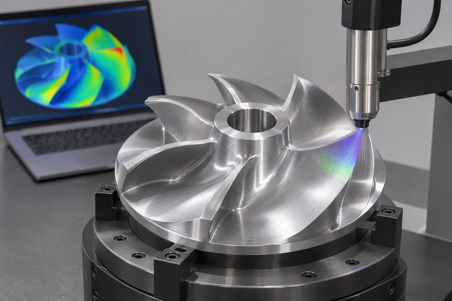
Why Impeller Quotes Vary So Widely
Two impellers with the same outside diameter can have very different manufacturing routes. One may have straight, widely spaced vanes that are accessible with short cutters. Another may use twisted blades, a tall hub, narrow passages, thin trailing edges, and an overhanging shroud. Diameter alone does not describe programming time, tool motion, cutter reach, workholding, inspection, or scrap risk.
The quotation normally begins with a manufacturing route. The supplier decides whether the hub and bore can be turned first, whether blade roughing can be completed from one orientation, whether indexed positioning is sufficient, and where continuous tool-axis movement is needed to maintain access and avoid collisions. The route also defines which surfaces can be completed while the part remains referenced to the same datum.
Starting stock matters as well. A solid billet offers known access but may require heavy material removal. A forged, cast, or near-net blank can reduce cutting, yet it introduces its own stock allowance, datum, incoming-condition, and minimum-order questions. A buyer should not compare a billet-based quote with a near-net-blank quote until the included material condition and incoming inspection are clear.
Manufacturing Route: Turning, 3+2, or Simultaneous 5-Axis?
The word “impeller” does not automatically make every operation a simultaneous 5-axis operation. Hub faces, the central bore, simple diameters, and accessible mounting features may be efficient on a lathe or in conventional milling. Indexed 3+2 positioning can orient the part for several fixed-angle cuts. Simultaneous 5-axis movement becomes valuable when the cutter must continuously change orientation to follow a twisted blade, reach into a passage, control contact near the cutter tip, or avoid interference with adjacent geometry.
| Process route | Best fit | Main cost drivers | RFQ question to resolve |
|---|---|---|---|
| Turning plus conventional milling | Open, accessible vanes with simple hub and bore features | Multiple setups, datum transfer, fixture time | Which relationships must be held in one setup? |
| Indexed 3+2 milling | Blade regions reachable from a series of fixed orientations | Number of index positions, reach, transition blending | Are all controlled surfaces accessible without continuous axis motion? |
| Simultaneous 5-axis milling | Twisted blades, changing draft, narrow passages, complex free-form surfaces | CAM work, simulation, roughing and finishing cycle time, tool reach | Which surfaces require continuous tool-axis control? |
| Near-net blank plus finish machining | Repeated production when a suitable blank route is justified | Blank tooling, stock allowance, incoming variation, finishing scope | Who owns the blank definition and acceptance criteria? |
| Two-piece or alternative construction | Closed passages that cannot be reached from solid stock | Joint design, alignment, assembly, distortion and validation | Can the design authority approve a split construction? |
A strong quotation explains the proposed route in functional terms. It does not need to reveal proprietary toolpaths, but it should make clear which surfaces are machined, which surfaces remain as supplied, how many major setups are assumed, and whether balancing, polishing, coating, or assembly is included. That information lets procurement compare like with like.
Blade Geometry Is Usually the Dominant Machining Variable
Passage width and tool access
Wide passages permit stiffer tools, easier chip evacuation, and more direct tool orientations. As the gap between blades narrows, the cutter and holder must still enter without contacting adjacent surfaces. The limiting feature may not be the cutting edge; it may be the shank, holder, spindle nose, or required tilt angle. A narrow throat can force a smaller cutter or a longer reach, increasing deflection and finishing time.
Blade height, twist, and overlap
A tall blade requires the tool to work farther from the supporting hub. If the blade twists substantially from inlet to outlet, a fixed orientation may not maintain a safe and effective contact point. Overlap between neighboring blades can hide surfaces from a straight approach. These conditions increase programming and simulation effort even before metal is cut.
Leading and trailing edges
Very thin edges are sensitive to vibration, handling, and burr formation. A drawing should distinguish a functional edge thickness from an idealized CAD knife edge. An infinitely sharp modeled edge is not a machinable acceptance criterion. If the hydraulic or aerodynamic design allows a defined minimum edge thickness and a controlled blend, the supplier can select a more stable finishing strategy and the inspector has a measurable requirement.
Fillets at the blade root
Root fillets influence stress and flow, but they also determine cutter size and reach. A larger, continuous fillet generally permits a stronger tool and smoother motion. A very small root radius may require a separate tool and additional passes, especially if the adjacent blade blocks access. Make the radius functional, consistent, and fully represented in the 3D model.
Datum Strategy, Bore Fit, and Runout
An impeller is a rotating component, so its bore, mounting face, hub, outside profile, and blade mass distribution are not independent. The drawing should identify the mounting interface used in service and define datums from those functional surfaces. Without a clear datum scheme, one supplier may reference the bore, another may reference an outside diameter, and a third may fixture from a temporary stock feature. All three can quote the same CAD file while assuming different results.
Specify a bore fit only after the shaft, retention method, assembly temperature, and service needs are known. Avoid copying a tight fit from another component without checking whether it is required. Likewise, runout should be applied between surfaces whose relationship matters in rotation. A broad runout callout on every visible diameter can add setup and inspection effort without improving function.
Where practical, keep the critical bore and mounting face in the same datum chain used for the blade finishing setup. If the part must be removed and rechucked, the route needs a reliable method to recover the axis. The drawing does not need to prescribe the fixture, but it should make the required relationships unambiguous.
Balance Requirements Must Be Quoted as a Defined Deliverable
“Balanced” is not a complete purchasing requirement. State whether the requirement is static or dynamic, the applicable acceptance standard or project specification, the balance grade or residual unbalance limit, the service speed and operating condition, and whether correction marks or removed material are permitted in defined zones. If balancing is performed by another supplier, define the condition in which the impeller leaves the machine shop.
Machining concentric features and maintaining consistent blade geometry can reduce the correction needed, but dimensional inspection is not a substitute for a specified balancing operation. Conversely, a balancing requirement does not replace limits on the bore, mounting face, blade profile, or runout. Treat them as related but distinct deliverables.
For prototypes, engineers sometimes need only dimensional parts for fit or flow testing. For production-intent hardware, balance documentation may be part of acceptance. Tell the supplier which stage the order represents so the quote does not include an unnecessary package or omit a necessary one.
Inspection Scope: Measure What Controls Performance
Free-form blade surfaces cannot always be accepted with calipers and micrometers. The inspection plan may use a coordinate measuring system, scanning method, section checks, templates, runout measurement, or a combination. The appropriate method depends on profile tolerance, surface accessibility, part size, material, and whether the drawing controls individual points, a surface profile, thickness, or the relationship to datums.
Inspection time can be substantial when every blade requires dense coverage. A practical drawing identifies critical zones instead of applying the tightest profile limit to the entire model. If only an inlet edge, outlet edge, sealing diameter, bore, and mounting face drive performance, distinguish them from general surfaces. Also define whether the 3D model is basic geometry and which drawing revision governs.
Ask for the evidence your quality system actually needs: a dimensional report, a first-article report, material documentation, balance results, or a simple certificate. Requiring all possible reports on a development prototype increases cost and review time. Requiring too little on a production release creates receiving risk. The RFQ should state the required deliverable rather than waiting until parts are finished.
Actionable DFM Checklist for an Impeller RFQ
Before sending the model, review the following items with the design owner:
- Identify the construction: open, semi-open, shrouded, or split. Confirm whether all controlled surfaces are physically accessible.
- Define stock assumptions: billet, approved near-net blank, or supplier-proposed route. State material grade and condition.
- Use functional datums: base the datum system on the bore, mounting face, pilot, or other real assembly interface.
- Control blade surfaces selectively: distinguish critical inlet, outlet, pressure-side, suction-side, root, and tip zones from general geometry.
- Replace knife edges: specify a manufacturable edge thickness, radius, or blend wherever performance permits.
- Review root radii: use the largest functional radius and avoid abrupt changes that force extra tools.
- State surface finish by zone: do not apply a fine finish to the whole part if only selected flow or sealing surfaces need it.
- Define bore and runout requirements: connect them to the assembly and operating function.
- Specify balance completely: include the acceptance basis, operating information, correction limits, and required report.
- Provide a revision pair: send the 3D model and 2D drawing with matching part number and revision.
- Mark allowed changes: identify surfaces where tool marks, blend transitions, deburring, or balance correction may be acceptable.
- State quantity and future demand: separate prototype quantity, validation batch, and expected repeat lot so the supplier can choose a scalable route.
These steps reduce hidden assumptions. They also help a supplier decide whether a mixed process—turning for the hub and bore, followed by multi-axis milling for blades—offers better control than trying to complete every feature in one machine.
Cost and Economics: What Actually Changes the Quote?
The second occurrence of CNC machined impeller cost in a sourcing discussion should lead to a breakdown of resources, not a generic price per diameter. Material matters, but programming, roughing, finishing, setup, inspection, and risk can dominate. A smaller impeller with narrow passages may cost more than a larger but open and accessible design.
| Kostenfaktor | Why it raises cost | Buyer action that may reduce uncertainty or cost |
|---|---|---|
| Large billet and high material removal | More purchased stock, roughing time, chips, and possible distortion | Allow a suitable near-net route for repeat demand, or review nonfunctional mass |
| Narrow passages and long reach | Smaller tools, lower cutting loads, more passes, collision constraints | Increase access or passage width where performance permits |
| Twisted or overlapping blades | More complex CAM, simulation, tool-axis control, and finishing | Identify which surfaces need full profile control |
| Very thin edges | Chatter, burr sensitivity, fragile handling, slower finishing | Define a minimum edge thickness or blend |
| Tight profile and finish over all blades | Dense finishing toolpaths and extensive inspection | Zone the requirement around functional regions |
| Bore-to-blade runout | Datum recovery, controlled setups, dedicated inspection | Use a clear functional datum scheme and realistic limits |
| Balancing and reports | Additional operation, setup, correction, and documentation | State the exact acceptance requirement and correction zones |
| One-off quantity | Programming, fixtures, and inspection are spread over one part | Quote prototype and validation batch quantities together |
| Hard or low-machinability alloy | Lower removal rates, tool wear, heat management, and risk | Confirm the alloy and condition are functionally necessary |
| Late drawing changes | Reprogramming, simulation, inspection-plan revision, possible scrap | Freeze model and drawing revisions before release |
Quantity changes the economics because programming, process planning, fixture preparation, and first-article work are largely fixed. However, multiplying a prototype price by production quantity is not a reliable budget. Repeated orders may justify better fixtures, preset tools, probing routines, near-net stock, or a different operation sequence. Ask the supplier to quote the actual quantities you expect rather than an arbitrary single quantity.
Be careful with apparent savings. Removing an inspection report can reduce price only if the receiving plan and risk allow it. Relaxing a blade profile can reduce finishing time only if the performance model accepts the change. Switching material can improve machinability only if strength, corrosion, temperature, and compatibility remain suitable. DFM is a controlled engineering decision, not a request to make the part merely cheaper.
What to Include in a Quote Package
A complete RFQ should include the native or neutral 3D CAD model, a PDF drawing, part number and revision, material specification and condition, prototype and production quantities, controlled surfaces, datum references, bore and mounting requirements, profile and finish callouts, balance requirement, inspection documents, any finishing or coating, packaging expectations, and the requested delivery destination. If a requirement is undecided, label it as a question rather than leaving the supplier to guess.
For a blade surface, indicate whether the model is the nominal master. For the bore, state the fit or limit dimensions rather than only a nominal diameter. For balancing, identify the acceptance basis and service data. For inspection, specify the report and sampling level. Those details let suppliers compare the same scope and reduce quote revisions after purchase order release.
Conclusion: Make the Functional Relationships Easy to Quote
The best impeller quote begins with access, datums, and acceptance criteria. Separate simple rotational features from complex blade surfaces, specify only the tolerances and finishes that support function, and define balancing as a measurable deliverable. When the model and drawing agree, the supplier can select an appropriate combination of turning, indexed positioning, simultaneous multi-axis finishing, and inspection.
If you are preparing an RFQ and want to understand the likely CNC machined impeller cost, upload your revision-controlled 3D CAD file and drawing for a free DFM review and quotation. Include material, quantity, bore fit, blade-profile requirements, surface-finish zones, runout, balance criteria, and inspection documents so the engineering review can focus on the decisions that affect cost and risk.


