
Fragmento destacado: The cost of a custom CNC turned aluminum lens barrel depends on how its lens seats, bores, retaining threads, and mounting datums are related, as well as the number of setups and the inspection required after finishing. To obtain a usable quote, send the 3D model and a drawing that identifies the optical axis, critical seat diameters and shoulders, finish boundaries, quantity, and an assembly acceptance method.
Introducción
A lens barrel can be a short aluminum tube on a purchasing spreadsheet. In an optical assembly, it is the mechanical reference that locates the glass, the retaining ring, the sensor or next optic, and sometimes an external mount. A barrel can pass an overall diameter check and still create a tilted lens if the seating shoulder, pilot bore, and mounting thread are referenced to unrelated surfaces. Conversely, a drawing that demands exceptionally tight tolerances on every diameter can make an otherwise ordinary part needlessly expensive.
The procurement question behind CNC turned aluminum lens barrel cost is therefore more specific than “What does a tube cost?” The useful question is which features establish the optical axis, how they will be machined in relation to one another, and how the supplier will verify them. Lauens CNC lists custom CNC turning for rotational components in metals, with material, fits, threads, and inspection reviewed against the drawing. That scope makes a lens-barrel drawing a suitable candidate for a turning DFM review; the exact geometry and tolerance capability still require project-specific confirmation.
This guide is written for an engineer or buyer preparing an RFQ for a prototype, pilot lot, or repeat order. It treats optics-specific design choices as cost drivers, shows where the drawing should carry controls, and explains why finishing and inspection must be included in the quote. It does not assume that a machining supplier is responsible for optical prescription or system performance. Those requirements need to come from the optical design and assembly team.
Análisis técnico en profundidad
Define the functional axis before assigning tolerances
Most lens barrels have several circular features: an external pilot, one or more internal seats, a retaining-ring thread, and possibly a rear mounting interface. The designer should decide which of these establishes the assembly axis. If the barrel registers on an external diameter, that diameter may serve as a datum. If it mounts on a threaded interface, the effective mating behavior and a practical inspection method deserve attention. Calling every surface “concentric” without naming a datum or measurement condition leaves suppliers to infer the requirement, and their quotes may not be comparable.
A robust drawing identifies the primary mounting datum, the axial seating datum, and the features that must be related to them. For a lens seat, the diameter controls radial location while the shoulder controls axial location and tilt. The shoulder needs enough width to support the lens without contacting the clear optical aperture or a chamfer on the glass. A small burr at the seat can defeat an otherwise accurate bore. Clear geometry and a suitable datum scheme often save more money than specifying an aggressive blanket ± tolerance.
One setup can simplify relationships, but it is not magic
Turning is efficient when the key cylindrical features can be cut from one clamping. The spindle axis provides a common reference for the bore, shoulders, and exterior features machined in that setup. A second operation may still be needed for a back face, cross hole, flat, or opposite-end thread. Each transfer introduces a chance to add runout or axial stack-up, so the route should be planned around the features that matter most to optical alignment. A purpose-built soft jaw or other workholding may be justified for a thin-walled barrel or a tight relationship between opposite ends.
Thin walls complicate this route. Chuck pressure can elastically distort a tube while it is being cut; after release, a round bore may become lobed. Material removal can also change stiffness. If the lens seat lies near a thin section, state the assembly fit that matters and permit the supplier to propose stock allowance, support, or a different operation sequence. A nominally tighter machine offset will not correct a geometry that moves after unclamping.
| Barrel feature | Functional question | Machining and quotation implication |
|---|---|---|
| Lens pilot diameter | How is the optic centered without excessive clamp stress? | Bore size and form may need a finishing pass and a specified gauge method |
| Lens seating shoulder | Is the lens supported at the intended annulus and axial position? | Shoulder face, burr control, and access for a facing tool matter |
| Retaining-ring thread | Will the ring clamp correctly without touching the optical aperture? | Thread form, relief, start location, and functional gauge may add operations |
| External mount or pilot | What locates the barrel in the next assembly? | Datum relationship may determine whether features should share a setup |
| Black finish or coating | Which surfaces need low reflection and which need controlled fit? | Masking, pre-finish allowance, and post-finish inspection should be priced |
This table is a drawing review checklist, not a universal tolerance chart. The acceptable bore size, shoulder geometry, and alignment error depend on the lens prescription, clear aperture, temperature range, and assembly method. The machinist can evaluate manufacturability and measurement; the optical engineer should decide the functional limits.
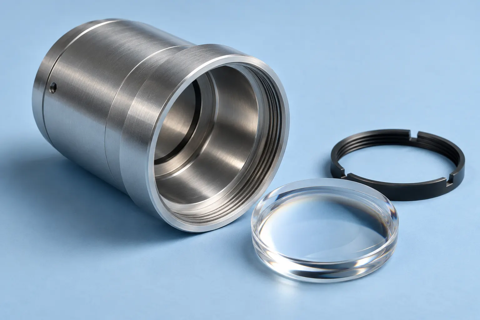
Thread geometry and edge condition are assembly issues
An internal retaining thread is often treated as a standard callout, but its runout, relief, and entry can change the assembly. If the ring bottoms before clamping the lens stack, the nominal thread may be correct while the product fails. If the thread entrance has a burr, the ring may bind or shed particles into an optical cavity. Specify the ring or mating component in the RFQ and, where practical, define an assembly check rather than relying only on a thread gauge.
A separate concern is the interface between metal and glass. A sharp corner at the seating shoulder can contact a lens chamfer or chip an edge during insertion. A broad unspecified edge break can remove too much support. Call out the intended contact annulus and the permissible corner geometry. If a seal or spacer sits between components, show it in the stack-up. The shop can then machine a purposeful relief instead of guessing at deburring.
Finishing can change a fit
Aluminum optical barrels are sometimes darkened to manage stray light or appearance, but the finish is a process input, not merely a color selection. A coating can add material to diameters and threads, alter friction, or affect how a lens seats. Specify which surfaces are to be finished, masked, or machined after finishing. If black anodizing is required, identify the color, process class if applicable, cosmetic criteria, and any protected precision interfaces. Do not assume a nominal “black anodize” note resolves post-finish size or surface texture.
Inspection should occur at the state in which the part will be accepted. A pre-finish bore measurement cannot prove a post-finish assembly fit if the bore is coated. Where a surface is masked, state that explicitly. If the optical cavity needs a cleanliness standard, describe the inspection and packaging requirement rather than using “clean” as an unpriced adjective.
Directrices sobre el diseño orientado a la fabricabilidad (DFM)
1. Put tight controls on interfaces, not on every diameter
Begin with the features that position glass or mate to another housing. Give those diameters, shoulder faces, and their relationships clear datums and tolerances. Outer cosmetic diameters and nonlocating reliefs can usually be assigned less restrictive controls if the assembly permits it. This helps the shop select where to use finish passes and detailed inspection. A drawing full of identical small tolerances provides no signal about which defect would actually degrade image quality.
2. Design the seat for the actual lens edge
Provide the lens outside diameter, edge chamfer, center thickness, and intended seat width or contact diameter. Show enough clearance at the bore entrance for assembly without scraping a coating or the glass. Provide a tiny but deliberate corner relief at the seat where needed. A machinist can cut and inspect a defined relief; “break all edges” is too vague for the interface that carries an optical element. If adhesives or O-rings are used, show their space and tolerance stack instead of assuming the lens will always bottom on bare metal.
3. Consider wall thickness after all bores and grooves
Inspect the thinnest radial section after the retaining thread, internal counterbore, and external groove are modeled. A seemingly thick tube may have a narrow ligament where those features overlap. That area can distort under chuck load, assembly clamp force, or temperature change. If the housing is long relative to diameter, consider whether a separate spacer or two-piece construction creates a more stable route. The right answer depends on the optical alignment chain and should be reviewed before the first quote is frozen.
4. Make the retaining ring a controlled mating part
Send the ring drawing or a reliable commercial part specification. Specify whether the ring must be removable, its installation tool clearance, and the permitted clamp load on the lens stack. A custom ring may need its own turning operation and inspection; a standard ring may constrain the barrel thread and face geometry. Either way, price the pair as an interface. Requiring a unique thread while omitting the mating ring is a common source of rework.
5. Place cross holes and flats where a second setup is justified
Set-screw holes, cable passages, and wrench flats can convert a straightforward turned part into a turn-and-mill route. If they do not affect the optical datum, allow a location tolerance appropriate for access and assembly. If they must register to a lens seat, show the relationship explicitly and expect a more involved setup or inspection. Avoid an unnecessary angular clocking requirement on rotationally symmetric features; it creates work without changing function.
6. Specify finish boundaries and inspection timing
Mark areas that must retain a precise fit or bare-metal contact, and state whether dimensions apply before or after the finish. If dark internal surfaces are needed for light control, identify the extent; if coating is prohibited near a lens seat, mark the exclusion. Define acceptable cosmetic variation separately from dimensional acceptance. A finish vendor and machine shop can then price the real sequence, including any masking and post-finish check.
7. Send an assembly drawing as well as the barrel model
A STEP model and 2D barrel drawing are essential, but the mating lens, ring, spacer, and external mount explain why certain dimensions are tight. If proprietary optical details cannot be shared, provide an interface control drawing with the critical sizes and datum chain. Include prototype quantity, intended repeat quantity, material grade, finish, and delivery need. A supplier can respond with a DFM alternative only when the functional limits are visible.
Desglose de costes y aspectos económicos
The practical way to compare CNC turned aluminum lens barrel cost is to separate one-time and per-piece work. Programming, process planning, first-piece setup, and any custom jaws can dominate a prototype. For repeat orders, boring cycle time, thread operations, coating yield, assembly checks, and dimensional inspection matter more. A quote that does not state whether post-finish inspection is included may appear cheap while leaving a critical acceptance step unpriced.
| Factor de coste | Why it changes price | How the buyer can clarify the RFQ |
|---|---|---|
| Bar stock and aluminum grade | Blank diameter, yield, and alloy availability affect material and setup | Specify grade, quantity, and whether an approved substitute is possible |
| Stepped bores and deep reach | Long boring tools may need slower cuts and additional passes | Identify only functional bores and permit realistic internal reliefs |
| Datum and runout relationships | Critical features may require common setup, special workholding, or detailed inspection | Define the mounting datum and relevant feature relationship |
| Retaining and mounting threads | Threading, reliefs, gauging, and mating-part checks add operations | Supply the ring and mount specifications with acceptance criteria |
| Finish and masking | Coating handling, masks, rejects, and post-finish checks add cost | Mark finished and excluded surfaces on the drawing |
| Inspection and cleanliness | Full reports, assembly trials, and protected packing add labor | Define sampling, report content, and packaging expectations |
Why tolerance language affects the quotation
“Concentricity 0.01 mm” can be interpreted differently if the reference feature and measurement approach are not named. A clear runout or position control, where appropriate to the design, gives the supplier a measurable target. Such controls should follow the part’s functional datum structure, not a generic preference for one GD&T symbol. If the lens barrel is measured on a temporary mandrel but used on a threaded mount, the test may not represent assembly behavior. Ask the supplier to describe the proposed fixture and gauge for the most important relationship before accepting a high precision price.
Surface finish can have the same problem. A roughness value on an entire internal wall may require extra tool passes and inspection even if only a narrow lens seat touches the glass. Identify the contact band and any surface that influences sliding, sealing, or stray light. If an optical black finish is expected to create the final internal appearance, an unnecessarily fine pre-finish on noncontact areas may be wasted cost.
Prototype versus production route
A single prototype should be evaluated for learning speed and fit risk. It may be worth using a simple holding method and measuring the key optical interfaces thoroughly. Once the design is validated, a repeat batch can justify dedicated jaws, process controls, sampling plans, and coordinated finishing. Request quantity breaks that match your program: one or two first articles, a pilot lot, and the expected release quantity. Do not extrapolate a one-piece quote linearly across a production order.
If the barrel design is still changing, tell the machine shop. It may suggest keeping a datum scheme and stock size stable across revisions so the route can be reused. Conversely, changing the lens seat, thread, or finish boundary after tooling and inspection fixtures are established may trigger new setup cost. A quote should identify what is included in the current revision and what would require requalification.
What to compare between suppliers
Collect the same requirements from each bidder: material grade, drawing revision, finish state, controlled features, inspection scope, mating-ring test, packaging, quantity breaks, and target date. Compare the quoted process assumptions as well as the piece price. One supplier may include bore gauging after coating while another measures before coating; the figures are not equivalent. Likewise, a barrel with a cross hole that is merely clearance-located is a different job from one whose cross hole must clock to an optical datum.
For a strong RFQ, ask the supplier to call out any feature it would relax, modify, or inspect differently. That creates an explicit engineering choice. It also allows the buyer to judge whether the proposed savings are real or simply transfer assembly risk downstream. The shop can advise on manufacturability; the optical system owner should approve changes to lens position, tilt, or stray-light behavior.
Conclusión y llamada a la acción
A lens barrel’s cost is set by the relationship between its functional interfaces, not by the amount of aluminum in the part. A precise bore, seat, thread, and mount can often be planned efficiently when the drawing shows the optical datum chain and finish boundaries. Extra operations become visible when thin walls, cross features, masking, or full inspection are required.
If you are budgeting CNC turned aluminum lens barrel cost for a new optical assembly, Sube tus archivos CAD en 3D a Lauens CNC with the 2D drawing, mating lens and ring interfaces, material grade, finish map, quantity breaks, and critical measurements. Request a free DFM review and a project-specific quote that makes the proposed machining and inspection route clear before you commit to production.


