
Fragmento destacado: The cost of a small-batch CNC-milled copper heat sink is driven less by its outer dimensions than by copper stock yield, the number and depth of fin slots, tool access, base flatness, and inspection requirements. A buyer can get a more reliable quotation by supplying the 3D model, drawing, thermal interface requirements, grade, quantity breaks, and acceptable alternatives such as a machined base with a separate fin pack.
Introducción
A heat sink drawing can look deceptively simple: a flat plate, a rectangular forest of fins, and four mounting holes. The supplier sees a different object. Each narrow channel must be cut without bending the neighboring fin, loading the tool with copper, or leaving burrs where airflow matters. The mating face must sit properly against the heat source after material has been removed from the opposite side. If the buyer specifies every surface to the same tight tolerance, the quote may reflect a metrology project rather than a practical thermal component.
For prototype and low-volume buyers, small-batch CNC milled copper heat sink cost should be evaluated alongside function. The lowest unit price is irrelevant if a warped base increases interface resistance, a crowded fin array starves the fan, or an unmachinable slot forces a redesign. Lauens CNC offers custom CNC milling and lists copper as a machining material; a drawing review is the right way to establish whether a particular geometry, quantity, grade, and inspection plan fit the available route.
This guide is for engineers and purchasers who already have a thermal envelope or CAD model and need to turn it into a quote-ready part. It explains where machining time accumulates, which dimensions deserve control, when an alternative construction may be worth comparing, and what information prevents a supplier from pricing avoidable uncertainty.
Análisis técnico en profundidad
Start with the thermal path, not the fin count
Heat must travel from the device through the interface material, across the base, into the fins, and then into moving air. Each segment can dominate. A thicker base may spread heat from a concentrated source, but it also adds copper, mass, and possibly machining time. More fin area helps only when air can pass through the channels at the available fan pressure. A very dense array can raise pressure drop and make cleaning difficult. Thus, a drawing that simply maximizes fin count can increase both manufacturing cost and operating temperature.
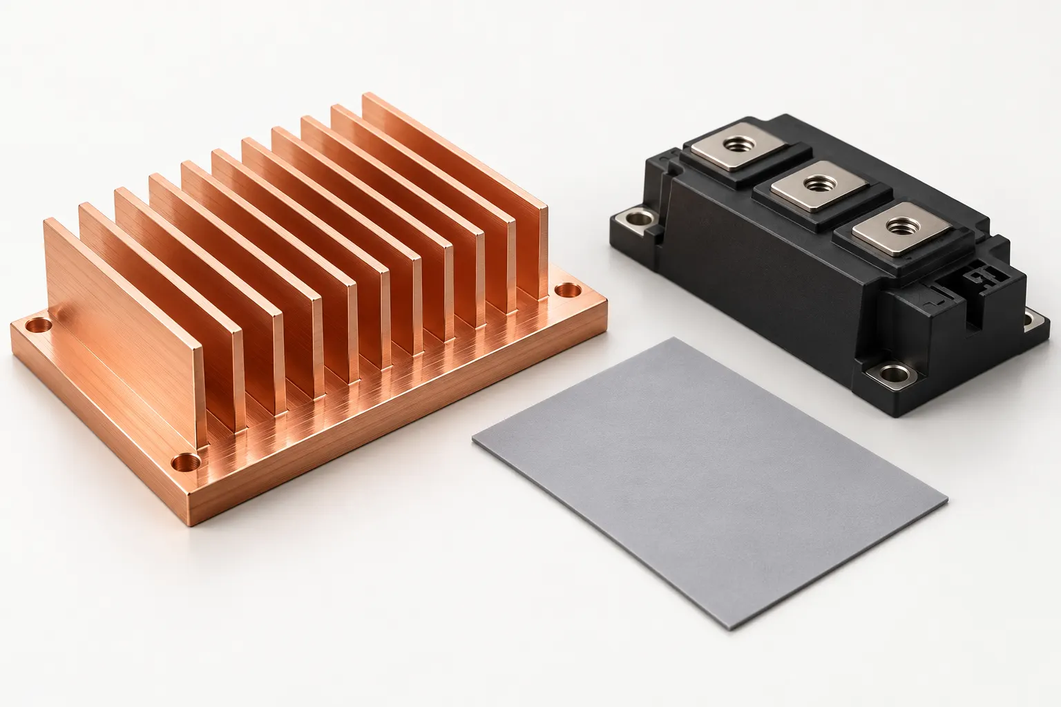
For an RFQ, distinguish the contact face from cosmetic faces. The contact face may need a defined flatness, roughness, and protected handling method. The fin tops often do not need the same controls. State whether the thermal interface uses grease, a pad, or another specified material, and whether the module is clamped at two or four points. Those choices influence how to inspect the base and whether clamping will correct or worsen distortion.
Why copper fin milling is expensive
Copper is valued for thermal conductivity, but its ductility creates machining challenges. A cutting edge that is not sharp can smear material rather than shear it cleanly. Chips can pack into a deep, narrow channel. A slender tool may deflect, causing tapered slots and uneven fin thickness. Thin fins can vibrate or bend during roughing, deburring, and handling. The practical sequence usually protects the base and the fin roots, removes bulk material in stable passes, and leaves a controlled finishing allowance where function demands it.
Slot width is a critical cost lever because it sets the tool diameter. Fin height divided by slot width is a useful screening ratio for tool access; as that ratio rises, stiffness and chip evacuation become harder. That is not a universal machinability limit. Cutter geometry, spindle capability, reach, grade, and fixturing all matter. Ask a supplier to review the exact CAD model before freezing a minimum gap. The same rule applies to inside corner radii at the bottom of the slots: a realistic radius gives the cutter room to work and can reduce extra finishing operations.
| Design choice | Machining implication | What to specify on the RFQ |
|---|---|---|
| Wider fin channel | Allows a stiffer cutter and more reliable chip evacuation; may reduce slotting time | Minimum permissible channel width and thermal airflow constraint |
| Taller or thinner fins | Raises deflection, burr, handling, and inspection risk | Functional minimum fin thickness and allowable cosmetic variation |
| Thicker base | Uses more material but may improve spreading and resist distortion | Heat-source footprint, mounting load, and allowable mass |
| Controlled contact flatness | May require a dedicated finishing and inspection setup | Datum, measurement area, flatness limit, and inspection quantity |
| Integral versus separate fins | Integral milling avoids a joint; a separate fin pack may use less slotting time | Whether an assembled alternative is acceptable for evaluation |
The table is a design conversation, not a promise that one geometry will meet a specific cost or tolerance. Thermal performance needs analysis or testing under the actual heat load, airflow, orientation, and interface conditions. Likewise, milling feasibility should be judged from the part envelope and toolpath, not an isolated fin-thickness number copied from another vendor.
Base flatness, burrs, and inspection strategy
The base can move when a large volume of copper is removed from one side. Residual stress, clamping force, and uneven material removal can all affect the finished plane. A good process plan therefore considers when the mating face is finished, how the part is supported, and whether the final inspection occurs in a free state or a defined restraint. The drawing should identify the datum and the contact patch that matters. Requiring a tight flatness across decorative overhangs may add work without improving thermal contact.
Burrs deserve the same attention as dimensions. Copper can leave a rolled edge around mounting holes and fin tips. Burrs in an airflow channel reduce clear width, and burrs on the contact face can hold a heat sink off the device. Define burr acceptance by location: a contact surface should be clean and protected; fin edges can have a separate, realistic edge-break requirement. Asking for a blanket aggressive deburr on every slender fin may deform the feature you intended to preserve.
Inspection should follow function. A sensible plan may verify the mating face, mounting-hole pattern, overall envelope, selected fin-channel widths, and visual burr condition. Measuring every fin on every piece can be much more expensive than sampling a stable process, especially in a small batch. If traceability or full inspection is essential, state that in the RFQ so the quotation includes the actual labor and report format.
Directrices sobre el diseño orientado a la fabricabilidad (DFM)
1. Set the widest fin spacing your thermal system permits
Before choosing a very fine pitch, check the actual fan curve or natural-convection arrangement. For forced air, the pressure drop through the sink must be considered with the duct and fan; for natural convection, orientation and unobstructed channels matter. If two fin layouts meet the same thermal target, quote both. Wider channels can permit a sturdier tool, fewer passes, cleaner chip evacuation, and simpler inspection. Document airflow direction so a shop does not optimize the wrong axis.
2. Separate critical geometry from descriptive geometry
Mark the heat-source contact patch, mounting hole locations, maximum envelope, and any keep-out areas as functional. Give the remaining fin geometry sensible tolerances that reflect thermal design margins rather than drawing defaults. Avoid applying a tight profile tolerance to the entire model when only the interface and mounting relationship matter. A datum scheme should relate the contact face to the mounting features in the way the assembly actually works.
3. Leave room for cutter entry and a real root radius
Square-bottomed, narrow fin channels imply a cutter that may be difficult or inefficient to use. Allow a root fillet or relief where it does not impair thermal contact or airflow. Keep adjacent bosses, connectors, and ribs out of the tool’s approach where possible. If a fin must stop short of an obstruction, consider splitting the design into more accessible rows or changing the mounting layout. Ask for a tool-access review while the geometry is still editable.
4. Keep mounting loads away from fragile fins
Put screw heads, washers, and clamps on the base or a purposeful boss, not on the fin tips. Provide practical tool clearance for installation. If the fastener compresses a thermal pad, define the intended stack-up and clamp condition. An uneven mounting scheme can bend a thin base even when the free-state flatness passes inspection. A few extra millimeters of support around the holes may cost less than specifying a very tight machined flatness to compensate for assembly distortion.
5. Reconsider the blank and the construction
For one-off and small-batch parts, a billet-machined integral design may be attractive because it avoids a separate joining process and accommodates custom mounting. At higher volumes or extreme fin density, extrusion, skiving, or a separate fin pack may deserve evaluation. Each method changes tooling, geometry, thermal joint, and qualification work. Lauens CNC should quote the verified CNC scope; if the design depends on another process, ask explicitly whether it can be sourced or whether the CAD should be adapted for milling. Do not assume a production route from a rendering alone.
6. Choose material and finish deliberately
Specify the copper grade and any conductivity or mechanical requirement; “copper” by itself leaves ambiguity. A material substitution can change conductivity, hardness, stock availability, and machining behavior. If the mating face must remain bare for thermal contact, identify it as a finish mask or protected surface. Coatings and cosmetic finishes should be evaluated for their effect on contact, corrosion behavior, electrical isolation, and assembly. Lauens CNC has a copper material page, but the grade and finish for a particular heat sink still need confirmation on the quote.
7. Supply a drawing that resolves thermal and mechanical questions
Send a STEP or other usable 3D CAD model and a 2D drawing with the device footprint, heat load, ambient or inlet temperature, airflow estimate, mounting pattern, interface material, contact-face requirement, and yearly and initial quantities. State whether a fan, duct, and enclosure are already fixed. A machine shop cannot certify thermal performance from geometry alone, but these details help it avoid recommending a cheaper shape that violates the real operating constraints.
Desglose de costes y aspectos económicos
The best way to evaluate small-batch CNC milled copper heat sink cost is to break it into repeatable and one-time components. The purchase price includes the blank, programming, fixturing, tool wear, cutting time, deburring, finishing, inspection, scrap allowance, and any packing that protects the fins. A longer quote with these assumptions can be more useful than a single attractive unit figure that excludes critical inspection.
| Factor de coste | Why it changes the quote | Acción del comprador |
|---|---|---|
| Copper grade and blank size | Raw material price, availability, and cut-off waste vary | Specify grade, permit a reviewed equivalent if acceptable, and provide quantity breaks |
| Fin count, gap, and height | More deep slots add toolpath length, delicate-tool risk, and deburring effort | Share thermal minimums and ask for a wider-gap alternate |
| Setup and workholding | Multiple orientations or custom support add nonrecurring time | Provide a stable datum scheme and allow fixture contact on nonfunctional faces |
| Contact-face finish and flatness | Dedicated finishing, careful handling, and metrology may be required | Control only the functional contact patch and state inspection method |
| Mounting holes and threads | Extra drilling, tapping, burr control, and verification add operations | Standardize fasteners and keep holes accessible |
| Quantity and inspection level | Setup is spread across more units, while full inspection scales with each unit | Request prototype, pilot, and production quantity prices separately |
Why the cheapest material is not always the cheapest part
Aluminum can reduce blank cost and mass, yet the overall solution may need a larger footprint, different fin geometry, or a different interface to satisfy the same thermal target. Copper can make sense for a concentrated heat source, but it is denser and often imposes greater material and machining costs. A fair comparison holds the duty cycle, temperature rise, envelope, airflow, mounting scheme, and qualification requirements constant. Do not compare a copper part quoted to a tight contact tolerance with an aluminum part that omits the same requirement.
One way to control risk is to request two quotations: the baseline copper CAD and a supplier-reviewed DFM variant. The variant might open fin channels, soften root geometry, simplify the mounting pattern, or narrow the flatness callout to the actual device footprint. The engineering team can then check whether the suggested changes remain within its thermal margin. Savings come from removing nonfunctional work, not from silently relaxing the requirement that makes the assembly operate.
Prototype and production economics differ
At prototype quantity, programming and fixturing can dominate the unit price. That does not mean the part is inherently expensive at an approved batch size. At production quantity, cycle time, tool life, burr consistency, and inspection throughput become more important. Ask for price breaks at realistic forecast quantities and a separate line for any first-article report, material certificate, or special packaging. If the design may change after thermal testing, explain that to the supplier; a flexible prototype route may be economically wiser than optimizing a feature that will disappear.
Schedule also influences economics. A rushed build may require stock on hand, simplified fixturing, or a higher-cost toolpath; a planned batch can permit a more deliberate process. Give the actual required date and distinguish prototype validation from production demand. Avoid substituting a generic “standard lead time” for a project-specific commitment. Geometry, material availability, inspection scope, and quantity determine the quotation and schedule.
What a quote should tell you
For a useful apples-to-apples review, ask whether the quotation includes the copper grade, number of setups, deburring method, protected contact face, defined finish, inspection points, and packaging. Identify any assumptions about thermal performance as design inputs supplied by your engineering team, not shop guarantees. If the vendor proposes an alternate pitch or fin thickness, request the marked-up drawing or model before accepting the price. That turns the quote into a controlled engineering decision.
Conclusión y llamada a la acción
A small-batch copper heat sink is quote-ready when the heat path, airflow, fin access, contact face, and mounting features have clear priorities. Fin density alone does not determine performance, and a blanket tight tolerance rarely identifies the real source of thermal risk. The strongest RFQ shows what must work, what may change, and how many parts are needed at each stage.
If you are comparing small-batch CNC milled copper heat sink cost for a prototype or production launch, Sube tus archivos CAD en 3D a Lauens CNC with the drawing, copper grade, quantity breaks, thermal interface details, and critical inspection requirements. Request a free DFM review and a project-specific quote, including a practical alternate geometry where one could reduce machining cost without compromising the functional requirements you define.


